Hello,
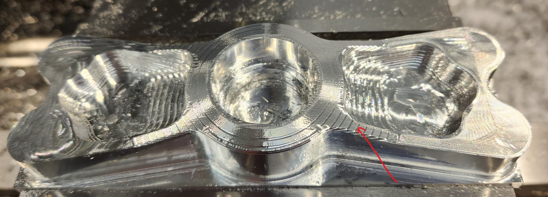
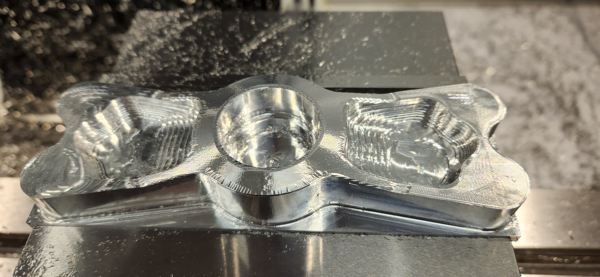
I am in the middle of machining the Titan 9M. I just completed the Parallel toolpath with the ball nose endmill. After running this toolpath, there are lines beneath what should now be a smooth surface (see image attached). For the initial Adaptive clearing toolpath I used a 1/2" endmill with a .030 radius. I can’t see how, but could the .030 radius be the culprit?
Thanks… Richard
2 Likes
@RichardSalzman did you leave stock in z in your roughing pass?
Yes. I left .01 radial and axial stock to leave. Thanks.
Did you define the .030" corner radius in your tools when using the adaptive?
How accurate is your ball nose endmill at the center? Can you check it on a comparator? You may add -.01" Z to your tool height offset to see if roughing grooves disappear.
Thanks Stephen. I did define the .030 corner radius. In fact I was impressed to see that the simulation was accurate enough to depict it. I will try adding -.01 to the tool height offset and see what happens.
Thanks as always… Richard
Hello,
I adjusted the tool height offset per your suggestion and it did indeed remove the roughing grooves. Thanksyou very much!
Unfortunately, there is one more issue. There are gouge marks around the perimeter of the part relative to this tool path. Please see attached. Any idea as to what could cause these? Is the lead in radius too small?
Fusion File: Dropbox - Titan 9M v60.f3d - Simplify your life
Thanks… Richard
1 Like
Experiment with the lead in and lead out radius, you can verify in your CAM if radius is too large.
Do you think this could be the cause? I realized that this toolpath does not have the ability to increase the lead in distance. My radius is set to .05.
Richard
Can it be a cause? Yes it can, that does not mean there are no other reasons you have a gouge. Stating that gouge is at the enter/exit place of toolpaths leans toward some reason a mark is visible. Feedrate may be too fast, there might be a dwell, a change in direction is too steep… There may be a gouge present before the finishing pass also… Richard the only way you can verify is watch it closely, maybe blue the surface after roughing and run the finish pass dry… change some feedrates, etc.
Thanks for the tips. Trouble shooting is a bit challenging because the parts from this course are the only parts I have ever milled on this milling machine. I literally just completed converting the mill to CNC. The previous 8 parts looked great. When there is a problem, I have to determine if it is a programing issue or machine issue.
Upon completing the CNC conversion, I learned that the ball nuts were faulty. I had the X and Y professionally repaired. They now work great and have less than 1/2 thou backlash. The Z ball nut has about .004 of backlash that is currently being compensated for with backlash compensation. At some point this ball nut will have to be repaired, but this is a major endeavor. I decided to see what limitations this backlash imposes before taking apart the whole rig.
The original image from this thread shows what the part looked like after the roughing toolpath. There are a few smaller gouges visible after this toolpath. My instinct is that these gouges are not a result of excessive Z backlash as they appear much deeper than .004.
I will experiment some more… Richard
1 Like
@RichardSalzman Great job fixing your machine. What control are you using Centroid?
Something else to consider on your part having lines in it. Did your rough tool pull out of it’s holder? How are you holding the tool is it ridged?
Thanks so much for that thought. I will certainly check to see if the tool has moved in the holder. I am using ER20 collets with TTS holders.
With respect to the machine, I am using CNC12 software and the Centroid controller with closed loop steppers. If you are interested, here is a link to the full build:
Another PM-833TV Conversion - CNC Mill Conversions and Builds - Dr. D-Flo (drdflo.com)
Thanks again for your thoughts… Richard
1 Like
I just wanted to share some really helpful information. Since I started this Titan’s Of CNC Building Block Series, I have rec’d fantastic help both on this forum as well as the Fusion 360 Manufacture forum. I posted this question on the Fusion 360 forum and here is a great video that was created to address the issues:
Video: (1) F360 3d toolpath tweaks - YouTube
I hope this may help others.
Thanks… Richard
3 Likes
I roughed with a 1/2" end mill with sharp corner and left .010 stock both ways, using adaptive clearing. Then for the center and pockets I used a 1/2" end mill with .120 radius, instead of a ball end mill. Seems like the middle section was ran using parallel and ofset to outer boundry. The pockets were ran using scallop. It came out very smooth.
1 Like