I have watched a lot of Titan’s building block cam videos and have not found and details describing how the Wear Compensation in Fusion 360 works, Titan just says “that’s what we do”. I’m having a hard time wrapping my head around the concept and how to implement it. If any one can shed for light on this or post a link I would be grateful
1 Like
Lets see if this helps - when you create toolpaths in Fusion, Fusion has to do the math to take into account the size of your cutter and then it offsets the gcode accordingly. Your machine only needs to run the gcode that was put out directly from Fusion. So the toolpath is 1,000% fixed - your end mill will never be able to move from this programmed path.
So what happens if after you run your part you find it’s running .002” out of size? There are so many reasons why this can and does happen - but you need perfection and need to fix this. But with no method to change the toolpath by that .002” to get the part perfect - how do you do it? Well you could redesign the part a little smaller and re-cam it, you could adjust your radial stock to leave and re-cam it. But this is a pain and not the right way to do it…
This is where using wear compensation comes in - wear compensation exists on your cnc machine controls in the tool setup area. As a tool wears, you can tell the control that that tool has worn by .xxx” and the machine control will then adjust all the tool paths by that amount.
Now picture your part is coming out too big as mentioned above - if you are using wear compensation. then you can just go into the tool setup page and enter a wear compensation number for that tool, and the control will adjust the toolpath automatically and move the tool either closer or further away from your part. Using this method you can dial in your finished part dimension. Easier than reprograming everything right?
BUT - in order to use the wear compensation you have to select use tool wear in fusion under”compensation type” on you finish passes. This will tell fusion to put the appropriate Gcode and Tool Wear Dimension call at the begining of code that is now going to be impacted by any tool wear dimmension you place into tool wear for the given tool.
So now you have an easy method to dial in the finished dimmensions of your part…
8 Likes
Thank you for your reply David, I think I get it and will play around with it
3 Likes
Is this the same as using regular cutter comp? Were you can inter a different diameter for the tool?
2 Likes
For the most part yes - with a little bit of difference.
It operates the same - except, wear is a separate number that you can track and adjust as you go. Without having to mess with the actual diameter that is being used for the cutter compensation. So 2 numbers doing almost the same thing - but just being separated so you can keep track of it better. And if you are using both of them, then the control will add both of these numbers together to get the total compensation it needs to apply to the new offset paths.
If you choose to use cutter comp(Coming from Fusion) you have to remember to put the diameter for that tool into your control at your machine - because Fusion is gonna write the code with no built in offset of any kind - it is however gonna tell the machine to go look up that diameter and do the offsets in real time as the part is running in the machine.
If you tell Fusion to use Wear instead of cutter comp - well simple, Fusion just generates the Gcode with your tool Diamter already accounted for in the X,Y it generates. You would now leave the tool diameter at your control set to “0” and now just adjust the tool wear number next to it as you run your FA and dial in your part.
So different strokes for different folks as to which method gets chosen.
IMHO - Cutter Comp was something we used more often when we were hand programing at the machine or running quick code, again at the machine. It allowed us to type in numbers that matched our prints, making it way easier to input and understand what the Gcode was going to be doing. If not we would have to stand there with a calculator trying to adjust every point and curve as we entered it.
With high speed tool paths, and code being pumped from Fusion etc. There really isn’t much need to use cutter comp anymore. So you’ll probably just stop using it, once you get use to posting the code and using tools from your library. (It’s just easier)
This leaves Tool Wear as your adjustment method for finish passes. It’s just nice and clean to just use it.
5 Likes
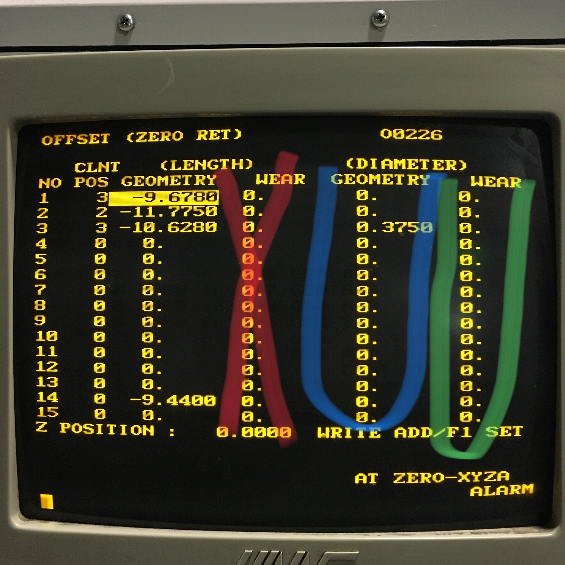
Take a look at this - This is something we are running now, It’s an older Haas VF2.
Blue = your normal cutter comp input area
Green = This is where you would input just the incremental wear adjustment.
Red = Don’t input here because this is for wear in the “Z” axis not your Diameter in X,Y
Note: This job is programmed by hand and I’m using cutter comp on Tool #3 so it needs the Diameter input here. I’m not using Tool wear for that tool, as these parts do not require that level of precision for the features being made.
4 Likes
Thanks David for taking the time to further explain this, really getting the concept now
3 Likes
If you are using a renishaw probe for your tools, using cutter comp and not wear is best though, correct?
1 Like
Unforunatley I do not have the experience to answer to that - we do not have probes.
1 Like
Personally I just use only wear for the endmill diameter compensation. Simply because you have much less chance of making scrap if the setter/operator forgets to input the correct diameter of the instrument.
2 Likes
I guess the reason this whear offset is strange to me is my Centroid control dose not have that option. So I will need to use in the control when finishing parts in Fusion 360.
Being self taught I might not have the best grasp on the cutter comp. When I program line and arks I always have a ramp line at least 1/2 the radius of the cutter the line just after turning CC on. I see in doing the CAM that that ramp line is non existent which kind of confuses me how it all works.
3 Likes
I totally understand where you stand. We always use what works for us. Let it be gearboxes in cars, or cutter comp in cnc 
For years I also worked on some Fanuc machines that never had wear option. It wasn’t until I was introduced to Haas machines, when I learned that there was so much more to setting up work or making corrections.
We, or atleast I learn something new everyday.
3 Likes
The plus for using cutter comp is if you regrind tools or don’t have the correct sized one at the time… then you can enter the actual diameter into the control, assuming you are doing repeat jobs instead of new ones.
Otherwise you would have to re-post the program with the adjusted tool size, if using wear.
2 Likes
I can definitely understand - took me a while to figure out cutter comp and wear comp, where to start your tool prior to turning it on and off etc - still not sure I have it down very well. BUT now that I do everything in CAM(for the most part) I hardly worry about cutter comp anymore, and just let fusion do it all. As long as I see the cutter doing what I want in the Fusion CAM simulation, I really never worry about it again. Post and go -
And even if your control does not use/have a tool 'Wear" specific feature - no sweat. Because you can still select “Wear” in fusion - and it will still work for you.
By selecting “Wear” as your compensation type in Fusion - it only tells Fusion to include a G41/G42 in the right spot of your code. The X,Y of the code Fusion kicks out will already be adjusted for your tool diameter. So in your control you would not have to enter anything in tool diameter. Because Fusion will automatically adjust your X,Y’s for the tool diameter(cutter comp) - but It is also still going to stick in the G41/G42 at the right spots of your code. This will make your Control look for and use a Diameter offset if one is input @ the machine - If you input any number in your tool diameter at the control this is going to end up being in ADDITION to your tool diameter which you already have taken care of in the Fusion code. So anything you enter in Tool Diameter in your machine will now act like a wear adjustment only.
Run your first article with tool diameter left blank - then measure your FA and then input JUST the adjustment amount in the Tool Diameter.
Controls that have “Tool Diameter” and “Wear” settings are only adding the two numbers together and then using the combined number to perform the G41/G42 offset.
2 Likes
With all of that - the descriptions of what you can pick for compensation type - should start to make more sense.
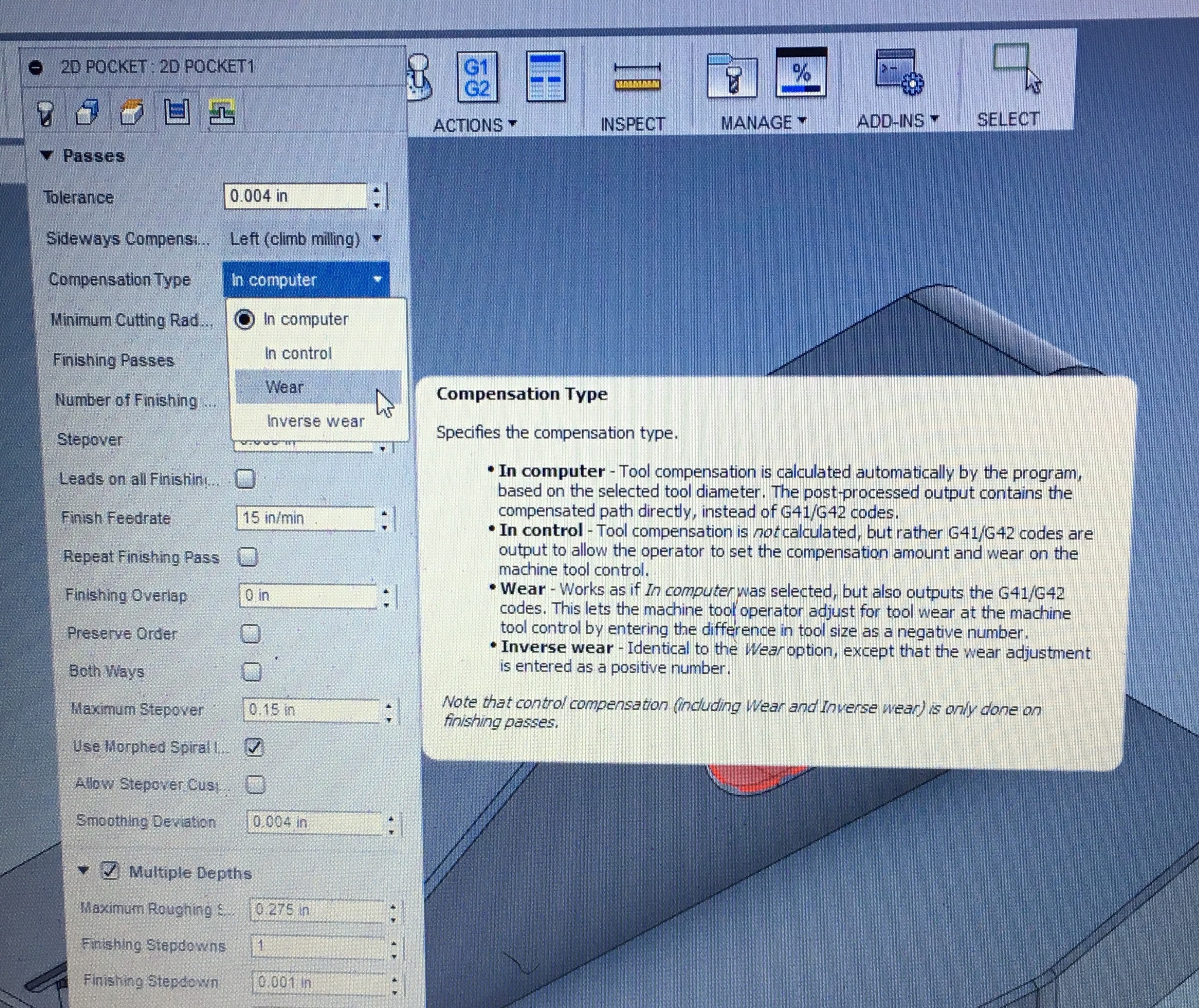
3 Likes
When you program with CAM software there are usually three types of comp used.
Wear comp is when the program is made for a certain size tool and you adjust for the dimension deviation in the machine control offset page.
Example, You use a 1/2 inch end mill to cut a pocket that is 2’’ X 2 " and the pocket comes out 1.995 x 1.995. so with wear comp you would make an adjustment of .0025 in your “D” wear value.
With control comp selected in your CAM software you would do the same thing just add .250 in the geometry column in your offset page.
The last style of comp I use is, computer comp. Whenever an adjustment to size needs made I make the change in my software and not at the machine. I would just adjust the cutter size in the tool description .