We all do the first op processes as shown in the academy. How do you handle the second op to complete the part?
2 Likes
My class worked this week on coming up with one 2nd Op clamp to hold several of the mill building blocks. Three of the four parts (3M, 4M, 5M, & 6M) have the 1.95 OD. We machined the pocket .600 deep so we could clamp all three parts by the diameter. The 4M with its triangle posed a slight problem. We wanted enough flat at the top of the triangle to center and hold position and still have enough flats at both of triangle to square things up. If I had them do it over again, might use a 1/8" endmill so the clamping surface for the triangle would be greater.
And after machining! We also learned how to add comments to the CAM program and set our G58 to be part of the post.


%
O06002 (Multi 2nd Op Titan)
(Using high feed G1 F500. instead of G0.)
(T4 D=0.25 CR=0. - ZMIN=-0.6 - flat end mill)
N10 G90 G94 G17
N15 G20
(.125 space between soft jaws G58 center of slot center of jaws)
(For Triangle, Use G57, Add Y+.0625)
N20 G53 G0 Z0.
(2D Adaptive3)
N30 T4 M6
N35 S5000 M3
N40 G58
8 Likes
I’ve seen this question ask before either in the form or on Facebook. You might try looking there.
1 Like
I cannot locate the original post I saw recently. It was either on the Titan academy FaceBook page or drilled down in one of the forum topics. So I am adding it to the topic about 2nd Ops.
How do you carry over the stock material to your next setup?
NYC Grismo saving material stock for next setup
2 Likes
This is AWESOME! With only one machine and 2 vises this will allow students to be able to completely finish 1M - 6M without changes. Great idea. We are pretty new to machining in general so ideas like this really help show how being creative can equal being more productive. Love it!!!
2 Likes
Currently, I keep one Mini Mill dedicated for this op (it also has a 5C vertical collet for some engraving projects we do). I have purchased a set of Shar Quick
Change jaws and will make some more soft jaws using the dove tail quick change design. Adding a .250” reamed hole in the soft jaw as reference, the student should easily be able to indicate the hole in and re-establish his work coordinate position when he
removes and replaces the soft jaws.

![]()
![]()
2 Likes
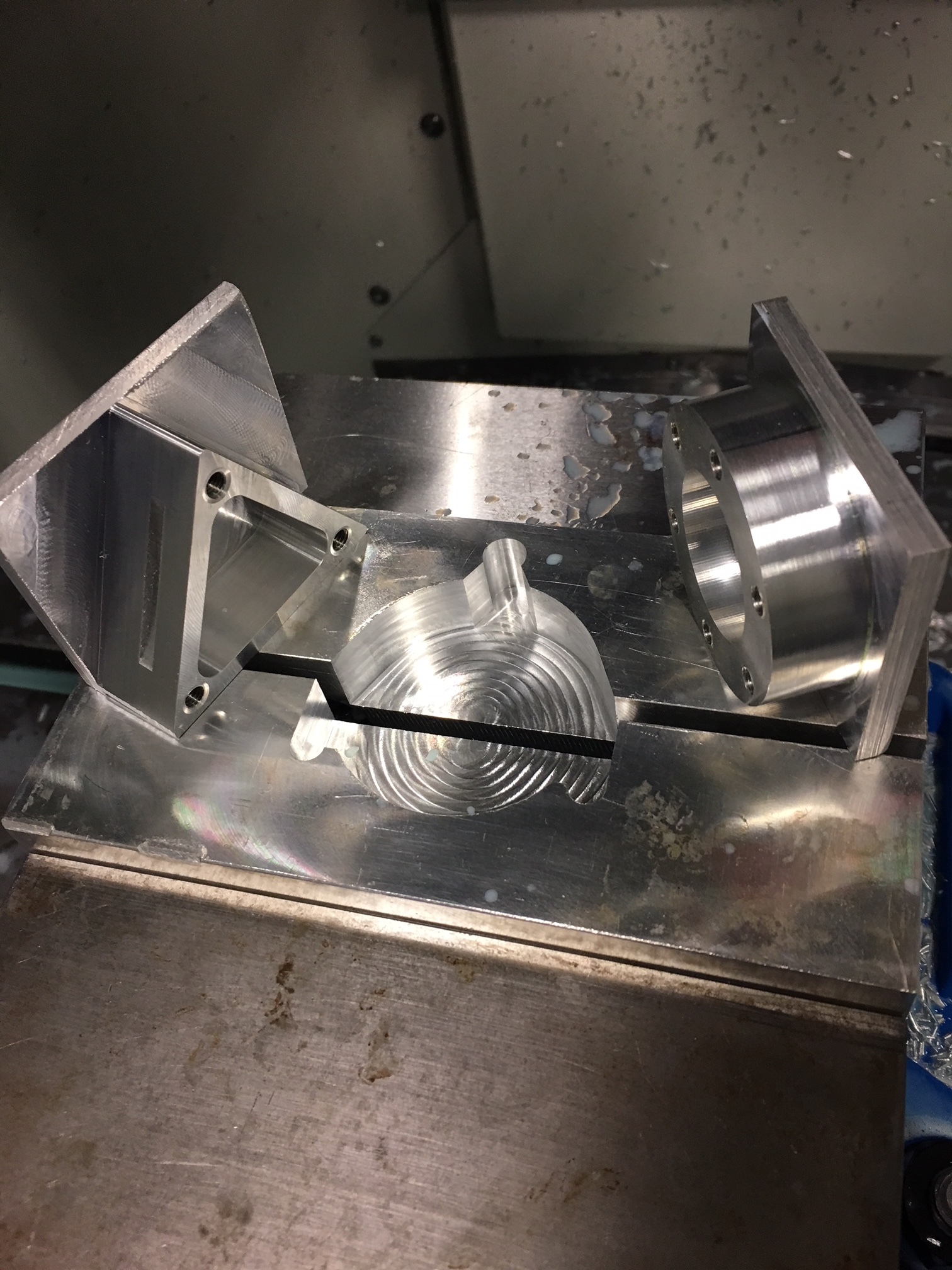
Good morning, been working on this combo softjaw and while close we are having issues with it marring the front of the 4m. Seeing how we’ve only made 1-2 sets of softjaws this is new territory for us. Any tips? I would imagine making these separate may have been easier but I like the idea of being able to have the same softjaws in vise 2 all the way through the 6M. Thanks.


4 Likes
In taking a closer look at the example above it looks like you have larger flats on the triangular front than we do. I’m guessing that could be one of the issues.
3 Likes
It will help. It has worked for me, we have run 15 parts and have no mars on the faces. Next time, instead of 1/4" relief in the corners, I will change to 1/8" relief. We will gain even more flat surface to engage.
6 Likes
Yes It does look like you do not have enough flat area on that one jaw and are actually pressing the fillet into the side of the part.
5 Likes
Update/Newbie Questions:
Got the softjaw cut so it no longer mars the part but need some help with proper setup. We modeled softjaw and part in softjaw in Fusion by placing origin on left of the rear jaw. What we noticed after removing the carrier material on the 4M is the chamfer may be heavier on one side than another. I’m guessing this is because students parts may be slightly different sizes or how the vise is tightened (although we are using a torque wrench) or???
Example of what we are doing for 4M
Contour around part leaving .050
Face carrier material
Chamfer triangular base
Engrave student name
Please advise on how you would go about doing this? We have had a similar issue with the 3m, 5m, and 6m as well where it seems like the center of our model in the softjaw on Fusion is not the actual center in the vise in the machine. We’re new and still learning and appreciate the help! Thanks!!
I forgot to mention that when cutting the softjaws we used a 1/2” parallel in between the jaws. Since we are not using that parallel when placing the actual part in the softjaws I’m assuming this may be why our center does not match the fusion model. How do you account for this?
3 Likes
My Y zero for the triangle was the edge of the fixed jaw. My Y zero for the diameter was -.0625 from the edge of the fixed jaw. I programmed each on its true center and not any edges. See image above “bore 2.jpg”
2 Likes
When setting up your parts in the machine how do you find the origin you set in the cam?
2 Likes
When I machined the softjaws, I placed a 1/8" thick parallel between jaws. My Y zero was the fixed jaw edge and I centered X zero about 3" from edge of jaw. I then set this as G58 for the triangle part. I then saved it to G57 and subtracted -.0625 from Y to establish the G57 coordinates.
Next time I have to make the jaws, I will add a .25 reamed hole in fixed jaw to establish a coordinate position away from program origin. If I was to lose my G57 or G58, I would place the 1/8 parallel and then indicate the diameter in.
3 Likes
Mt thoughts on 2nd op coming from Industry - Location. We generally would program round or symmetrical parts around C/L and drill a hole with a know location to find the center on Jaw reinstall and use - we had to document where the hole was in relation ship to X0Y0.
I am changing my mine with the CadCam simulation. I am making the standard for making the jaws - set XY to upper left corner with no shift. then make the jaw. and make a drawing to document for review with out having to look at Cam file. maybe even engrave the jaw with instructions what its for and where is XY
then in op 2 drag in the jaws as components and join them to the Model orientation and use upper left xy as location and Z locate off bottom and shift as needed to make thickness needed.
2 Likes
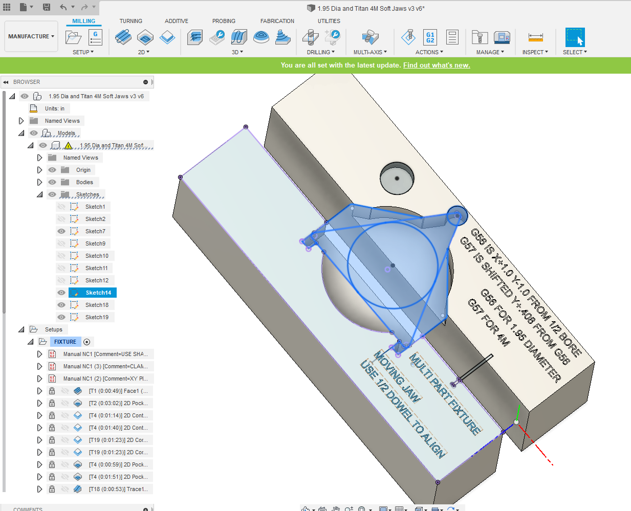
To increase the flat area for the triangle at the top, we changed it by adding a 1/2" spacer between jaws versus the 1/8". This allowed us to move the triangle contour down about .400". @DrewQuan when we designed our jaws, we projected the 4M onto the jaws. We centered the 1.95 part between the jaws, then added a 1/2" bore shifted 1" in X and Y to recapture positions when we changed out our jaws.
1 Like
When milling Op2, use the same exact origin that you used when milling the jaws. As long as your part and the jaws are properly modeled, it should give you a perfect result.
2 Likes