I am just starting on the Titan 7M. So far, this online course is fantastic! Are there directions that I am missing to mill the reverse side of the part?
Thanks… Richard
I am just starting on the Titan 7M. So far, this online course is fantastic! Are there directions that I am missing to mill the reverse side of the part?
Thanks… Richard
If you progressed thru 1-6M, then your only concern will be how to clamp it. You can cut a partial profile in softjaws, or clamp in hard jaws. I used the counterbore holes with mitee bite expansion plugs. When you flip the part over in Fusion to remove the .230" remnant, you just need to find your work offset location you decide to use. Match it to your program setup. I suggest you use something other than G54 for your 2nd Op, you will need to establish a new Z work offset. Here is a link to another topic in this forum. Titan 7m Op2 Simulation + Stock + Vice jaws - The Academy - TITANS of CNC: Academy
Another forum topic regarding 7M 2nd Op Titan 7M needing a little nudge in the right direction - The Academy - TITANS of CNC: Academy
Thanks Steve. Very much appreciated!
Hello Stephen,
Just a quick question. Someone commented “When it faces the final pass, the large remnant is violently thrown and occasionally the offending insert that was engaged when the remnant released from body was also fractured or thrown out of facing head. I would like to think this is happening to others also. So instead of facing the part first, I ran a contour pass with .050” offset around the outside contour, then faced the part"
Is the approach of running a contour pass something that is typically done or is it better to take multiple depths of say .07 to avoid this problem. As I am totally new to this I am just curious how this is typically handeled?
Thanks… Richard
Depends on how rigid your clamping method it. I ended up rough contour with a 3/8 endmill full depth (.230"). then faced off with face mill (multiple depths), finish contour, chamfer, engrave name.
Thanks for your help.
Sorry… One more question.
If you are going to face the second side, then the reference to the model is not that critical. But if you want to put a chamfer on it then it seems like you would need to precisely reference the model. Doesn’t this mean that you need to machine the at least the front & rear edges of the stock so when you flip it over to finish the second side you are referencing off a machined surface rather than the rough-cut stock?
Thanks… Richard
You are correct the XY must be referenced, either by a hard stop (fixed jaw and edge stop using a 1-2-3 block in a vise). In my setups I drilled thru and used (4) mitee bite expansion plugs to clamp on the counterbores. The holes became my reference. Check out my project listed on my cncexpert page. CNC Expert
Thanks. I was just finishing the 8M and was going to chamfer the edge. I just realized this would not be possible since I no longer have a reference to the model.
The 8M project has a soft jaw fixture portion you need to complete. Machining the profile of part in soft jaws will provide you the model reference to chamfer edges.
Hello Stephen,
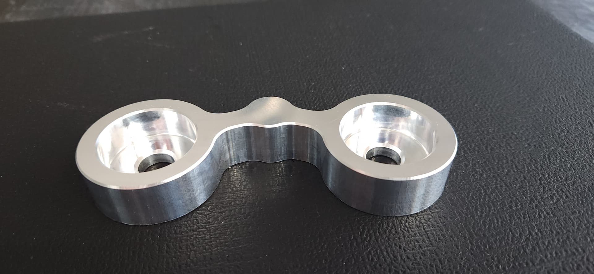
I think I confused myself here a bit. I did machine soft jaws and machined the Titan 8M (see image). Here is what I did.
I established my part zero location (G54) and machined the top of the Titan 8M from the stock.
I screwed the 2 x 1 x 6 soft jaw material in the vise. I established a new part zero location for the soft jaws. This part zero location was in the center of the top surface of the soft jaws. I then machined the profile of the part into the top of the softjaws .300 deep.
I put the part into the soft jaws and established a new part zero location (center of the part and .230 below the top of the stock) and then used the face mill to machine off the excess .230 material.
Here is the Fusion file for clarity:
At this point if I try to chamfer the bottom leading edge of the part, it will not register with the model because the stock that I started with had rough cut edges and I have nothing to reference from. What am I missing here?
Should I have used the SAME part zero position that I used to machine the soft jaws and created the toolpaths with this part zero position to face and chamfer the part?
Thanks… Richard
You are almost there. Use the same XY work offset for fixture zero for your model… Change the Z for that offset from bottom of soft jaw profile +.750. Make sure you change your 2nd Fusion op to be center of part top of part. On your stock profile in setup, add +.230" to top of model.
Stephen… Thanks for all your input! I think the confusion here is that I did not actually model the soft jaws for the Titan 8M. I used the same approach that Titan did for the Titan 3M using the profile of the part to machine the soft jaws.
If you don’t mind looking at the tool path “Face II” in the Fusion file below, I went back and used this same setup for machining the soft jaws as the final setup to finish the second side of the Titan 8M. Please let me know if this looks good as I did not save the G54 position to be able to test it. While I think this approach will work, it may not be the best.
Fusion File:
Thank again for all your help… Richard
@RichardSalzman The stock size for your 2nd Op for Z+ should be .230 not .750. You faced to model top, you need to face using multiple depths, I usually set mine to .075" per pass. You used G54 for your work offset, that is okay, I usually use something other than G54 for all 2nd Ops. If you clamp the finished 1st op between vise jaws, you could split the distance between jaws to set your Y zero. To get the X zero, a hard stop on LH of part, then add +2.725 from hard stop. This will place your program zero as per the file you attached.
Thanks for you help Steve.
I must be missing something here. I I am still confused as to how I can register to the soft jaws once they are removed from the vise. When I machined the soft jaws I established my part zero by moving in from the left side of the stock. This edge was a rough cut edge so my X position is approximately half way across the part. If I put the soft jaws back in the vise there is lateral movement (from the socket head screws) so my X position is not precise. I don’t see how I can precisely locate the model if I wanted to run the part again.
You previously noted:
'If you clamp the finished 1st op between vise jaws, you could split the distance between jaws to set your Y zero. To get the X zero, a hard stop on LH of part, then add +2.725 from hard stop. This will place your program zero as per the file you attached." I am not following this explanation.
Sorry for all the questions… Richard
@RichardSalzman - the previously noted section is for clamping part between hard jaws only… I would set a hard stop for X axis, Use a 1-2-3 block to set against hardstop and edgefind the X axis, set zero, than add half the length of your part. This will put you X center of your part. After clamping the part in vise, if you center between the two jaws, this will be your Y Center. If you use soft jaws again that is machined to a shape, I recommend you add a locating hole or bore in the jaw as reference to pick up next time you use jaws. ------- If you made jaws without machining a reference you can machine a plug same diameter as one of the eye pieces. Clamp this plug and indicate it in. Then shift X and Y to center of part +1.750 for X and zero for Y
Thanks. Yes. We are now on the same page.