For the mill-based Building Block drawings, there is a general note on each sheet to break all edges to .01 chamfer.

When I see the word ALL used that means every edge on every face in my book.
Top, bottom, left, right, front, back and also on any created features
Is that correct or should it not be taken so literally?
Thanks
1 Like
Yes, unless edges are noted otherwise. Look at the model.
1 Like
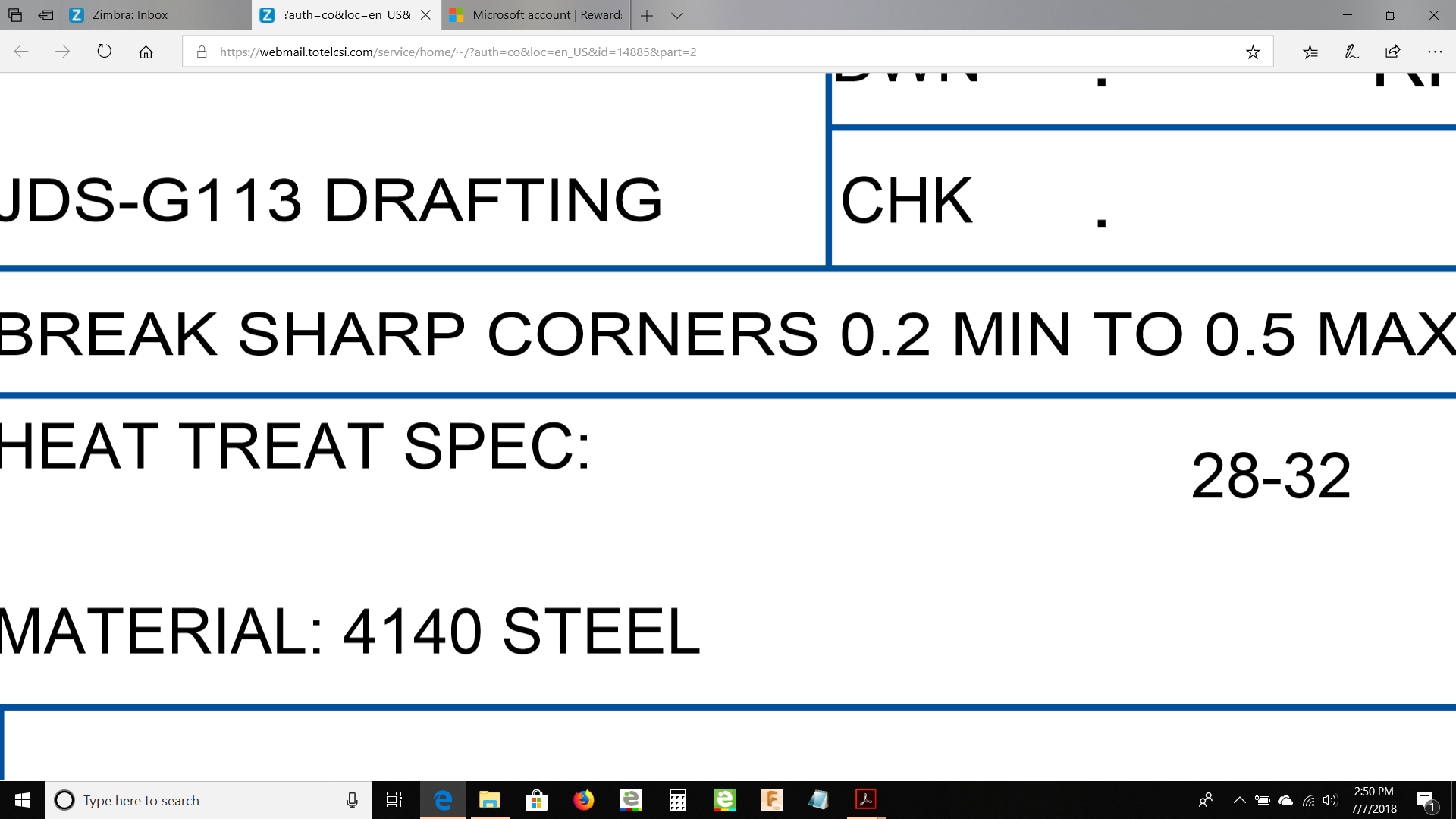
This note comes on most prints in the tolerance block.
There seems to be a discrepancy with edge chamfers in the post processing. If you leave the model edges raw and create the CAM chamfer operation they work just fine, but if you model the actual chamfers before creating the CAM chamfer operation, the tool will barely engage the material.
When you model the actual chamfers, you will end up with an upper edge and a lower edge that can be selected as your geometry OR you can select the actual face of the modeled chamfer between those lines. I just ran across this late last night and was not able to experiment with using various selections to see if anything ran differently.
Any thoughts here? Maybe just NOT model chamfers at all.
Thanks
1 Like
Answered my own question, I found a YouTube tutorial video that said to use 2D Contour on modeled chamfers instead of the 2D Chamfer and the simulation looks a lot better.
2 Likes
Hello, I am working on the Titan 4M. I have completed most of the design work for the Building blocks and now going back to do the CAM and machining. I have run the 1st op part complete and now working on the Titan Inspection sheet to verify all my dimensions. I am not sure how to measure the center location of the 2" radius that is cutting the three side slots. There is a Y dimension of 1.949 and a X dimension of 2.222. I do not have access to a CMM. There must be some way I can conventionally measure this.
1 Like
